


Montana State University
Spring 2015 - Fall 2015
The objective of this project is to design an electronically controlled, adjustable telescopic lens system to be placed in the path of an Nd:YAG solid-state laser beam. These solid-state lasers typically experience a phenomenon known as "thermal lensing", which is a de-collimation of the laser beam due to a thermal gradient that is dependent on the pulse repetition rate of the laser. By changing the focal length of the telescopic lens system to match a given pulse rate, optical stability can be achieved for optimal performance of the laser.
System Goals and Constraints:
- Adjustable focal length from -0.5m to -10m
- Electronic Control
- 40mm x 40mm x 60mm Size Limitation
- Magnification must stay in the x1.0 to x1.1 range
- 1/2" Diameter, Fused Silica Lenses
- Heather Giacomo -[Electrical Engineering]
- While Heather originally hails from Wisconsin, she spent the majority of her life in Northern California before finding her true home in Bozeman. Heather is in her senior year at MSU working toward a degree in Electrical Engineering with a minor in Optics. She will be graduating December 2015.
- While Heather originally hails from Wisconsin, she spent the majority of her life in Northern California before finding her true home in Bozeman. Heather is in her senior year at MSU working toward a degree in Electrical Engineering with a minor in Optics. She will be graduating December 2015.
- Spencer Hopkins - [Mechanical Engineering]
- Spencer is a senior in Mechanical Engineering at Montana State University who is planning to graduate in December 2015. His academic interests lie in the fields of engineering design, optics, and material science.
- Spencer is a senior in Mechanical Engineering at Montana State University who is planning to graduate in December 2015. His academic interests lie in the fields of engineering design, optics, and material science.
- Bryce Iverson - [Electrical Engineering]
- Born and raised in Billings, MT. Moved to Bozeman, MT, to study Electrical Engineering at Montana State University.
- Born and raised in Billings, MT. Moved to Bozeman, MT, to study Electrical Engineering at Montana State University.
- John Mulford – [Mechanical Engineering]
- Born in Cody, WY, and grew up in Billings, MT. After graduating high school, went on to study Mechanical Engineering at Montana State University. Currently pursuing work in the power industry and interested in pursuing a career in energy management. See John's LinkedIn profile.
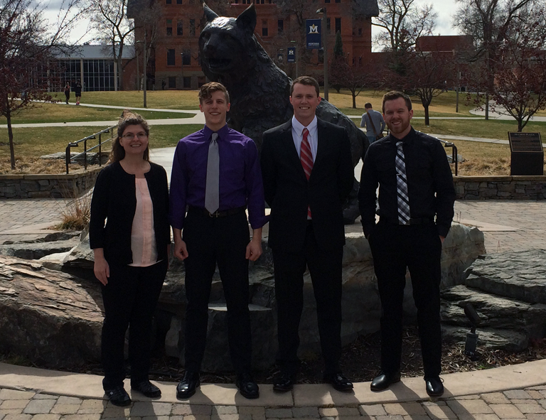
From the left: Heather, Spencer, John, Bryce.
Project Advisor: Dr. David Dickensheets, PhD, MSU
Technical Representative: Dr. Justin Togersen, PhD, Quantel-USA Inc.
Proudly Sponsored by Quantel-USA Inc.
Problem Background and Introductory Research:
In order to gain a strong understanding of the scope of this project, preliminary research was conducted over a wide range of topics relating to optical, mechanical, and electrical design.
The phenomena of thermal lensing was researched; this optical response is what drives the need for a telescopic lens compensation system. Thermal lensing is a result of the gain medium (laser crystal) heating non-linearly across its cross-section. This radial heating pattern results in the light exiting the laser crystal to be converging and thus uncollimated. Thermal lensing is what drives the design parameter of compensating for focal lengths between -500 mm and infinity.
Once the concept of thermal lensing was better understood, further background research was performed looking into lasers and laser safety. A laser, or Light Amplification by Stimulated Emission of Radiation, is a device which emits light; laser light differs from normal light, however, in that the emitted light is focused into a beam at a single wavelength. The ability to be focused and pulsed makes lasers useful for a broad range of applications including spectroscopy and non-destructive material testing. This focused, high-energy nature also can be dangerous and as such, precautions must be taken to protect oneself from harmful radiation. These harmful effects can easily be mitigated through proper eyewear and clothing. The proper protection for each specific laser can be found in the ANSI Z136 standards.
Another topic which was researched was optics. Not only were first-order optical systems studied in order to gain a basic understanding of how they behave, but telescoping systems, autofocus, ray tracing, graded index (GRIN) lenses, and ABCD matrices were also researched. The team’s design solution involves a refracting telescope under a magnification constraint, so a background in how these optical systems function was necessary. Phase detection autofocus serves as a tool in many optical devices (such as cameras) and operates by projecting light onto charged coupled devices in order to gain feedback and maintain focus. GRIN lenses are materials which have a refractive index which varies with position.
The most useful tools for optical design were ray tracing and ABCD matrices. Ray tracing follows the path of light through a lens using three vectors. In conjunction with ABCD matrices, the mathematical tool for predicting the ray path through lenses, a script was developed in MATLAB to trace the rays of light and thus design a system which retains beam collimation.
A system by which to actuate the dynamic lens was required, so preliminary research into actuation methods and materials was performed. Stepper motors operate under the principle of dividing one full rotation of the drive shaft into increments, or steps. These steps are very precise and the type of motor is useful for systems which translate rotational motion into linear motion. Feedback systems were also analyzed. Due to the nature of actuation, backlash can create undesirable positioning; a feedback system can supply information about position independent of external influences.
Piezoelectrics and shape-memory alloys (SMAs) were researched as potential solutions for the purpose of actuation. Piezoelectrics are a unique class of material which turn mechanical strain into an electric dipole, and alternatively physically deform when a charge is applied to them. The relationship between the mechanical and electrical properties of piezoelectrics is very predictable which makes them desirable for high-precision applications. SMAs are another unique class of material which can be plastically deformed, yet return to their original crystalline structure after a charge is applied or it is heated. In its martensitic phase, each defect pairs with a counter-defect, creating a herringbone structure.
Critical Subsytem Demonstration:
INTRODUCTION
The Critical Subsystem Demonstration (CSD) was an opportunity for the team to physically demonstrate that the most important aspect of the design would not only function, but be feasible. The team chose the lens system to be the most critical subsystem, since if the lenses did not correct thermal lensing, then the system would be ineffective. Preparation for this demonstration in the laser lab led the team to the discovery that their chosen lens system was faulty for this particular design. The source of this design error was found within the MATLAB script. This error was promptly rectified and a new lens system was chosen to demonstrate that the correction of thermal lensing was feasible.
The critical subsystem was demonstrated using a HeNe laser. A telescope and neutral density (ND) filters were set up in front of the exiting beam; the telescope magnified the beam such that it would fill the reticle of the wavefront sensor, and the ND filters reduced the intensity of the light so the wavefront sensor would not be oversaturated. A wavefront sensor reading was then taken in order to prove collimation of the beam. After this initial reading, a ‘thermal lens’ was added in the beam path to cause the laser to converge. This thermal lens was a -500mm focal length optic. After passing through the thermal lens, another wavefront sensor reading was taken to demonstrate that the beam was converging and thus, no longer collimated. The team’s critical subsystem, consisting of a plano-concave lens followed by a plano-convex lens, was then utilized to both re-collimate the beam, proving its capacity to correct thermal lensing. The critical subsystem was then set to not interfere with the beam, showing that if collimated light entered the system, it could pass through without changing its radius of convergence. Both of these states had their beam properties measured by the wavefront sensor
The CSD was instrumental in applying the knowledge gained from preliminary research as well as gaining hands-on experience in the laser lab. It was also taught the necessity of verifying mathematical models before moving further in the design process.
PROCEDURE
Using a Shack-Hartmann wavefront sensor to detect beam collimation, we set up the demonstration as follows:
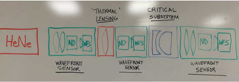 Figure 1: Visual schematic of the critical subsystem.
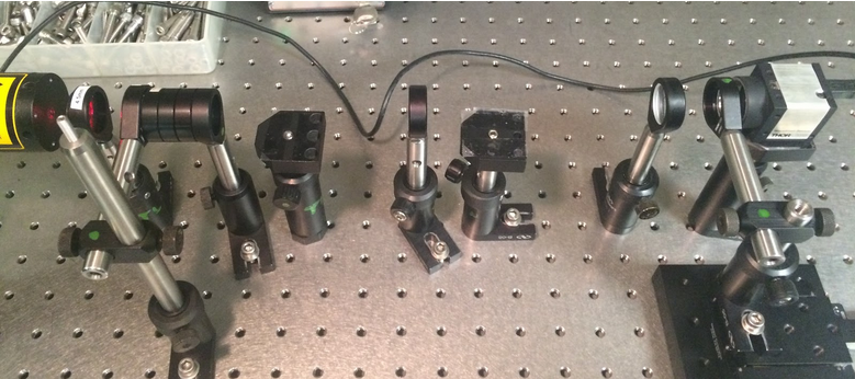 Figure 2: Photograph of the critical subsystem arrangement. MSU Optics Laboratory.
First, the beam needed to be enlarged to fill the wavefront sensor to make adequate measurements. Next, the beam intensity needed to be decreased so as to not oversaturate the wavefront sensor. A beam expander and ND filters were introduced before our “thermal lens”. We used a 500mm converging lens to simulate beam convergence at 1/2m. We measured the beam’s radius of convergence (ROC) after the beam expander to show collimation (infinite ROC) and after the thermal lens to show the beam was converging at 1/2m (500mm ROC). We then introduced our lens system at the necessary distance between them to show correction for this convergence and found the ROC to be very high again, showing collimation. Finally, we separated our lens system to the necessary distance to show that when the beam is collimating slowly as in convergence at 10m away, our system will not interfere with the beam quality. We were able to show a nearly 500mm ROC again.
CHALLENGES
During the set-up of the critical subsystem it was discovered that the lens focal lengths we had chosen previously were not capable of correcting the beam at the distances we had wanted. An error in the MATLAB code led us astray. After many iterations using the thin lens equation and simulations with lab equipment, we were able to demonstrate a lens combination that would work to correct the beam at one distance between them for 1/2m convergence and at another distance between them for 10m convergence.
CONCLUSION
We found -75mm and 100mm lenses that worked for the demonstration, however, the magnification was out of spec. Which led to further exploration of lens choices.
Critical Design Review:
OPTICAL SYSTEM
After much review, we settled on -55mm and 65mm focal length lenses which gives the following specifications for correction at 1/2m and 10m.
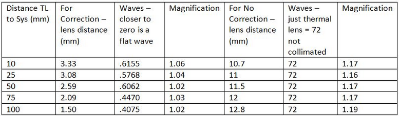 Figure 3: Computational estimation of beam correction for collimated and uncollimated beams using Zemax.
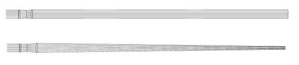 Figure 4: 2D view of the Zemax calculations. The two different distances give the shown collimated and uncollimated beams.
The resulting magnification was still a little too high so that has been the focus of design during the last week.
MECHANICAL SYSTEM
The design of the telescoping lens system went through numerous iterations before a final design was settled upon. The driving constraint in this iterative process was the size envelope under which the assembly must lie. This constraint required not only a very small motor, but also a very small translation stage. The translation stage was difficult to develop because most micro-sized, high-precision models were still too large for the team’s given size envelope. This size limitation inspired the team to utilize a pre-existing model, yet modify it to fall within the required size constraints. Once the design for the actuator was chosen, a motor was selected which would gear in parallel with the actuator, yet still fit within the tight size constraints.
Another design challenge to overcome was the mounting of the lenses. The lenses need to be mounted completely parallel to each other, within about 1 mm of each other at their closest, and able to be x-y translated to fine tune their positioning. The pre-existing mounting solutions with x-y capability from online vendors were much too large for the purposes of this project, so a set of custom lens mounts were drafted up in SolidWorks. These mounts utilize a system of set screws and springs in order to actuate the lenses on the micro scale; this allows for the necessary positioning such that the lenses will sit directly in the beam-line of the laser.
Once the actuator, motor, and lens mounts were chosen, a means of affixing each piece its mate, as well as mounting the assembly was required. The static lens mount was designed to replace the backplate of the actuator, so that it would be an intrinsic part of the actuation system. The dynamic lens was mounted to the collar of the actuator, allowing it to be driven by the micrometer power screw. The actuator with lens mounts attached was then mounted to a base plate which also holds the stepper motor. This entire assembly was iteratively redesigned in order to fit into the tight size constraint.
The current mechanical and optical design solutions are currently under modification. The belt drive mechanism shown below will be replaced with a gear system consisting of two to three gears. This is due to out-gassing and particulate forming of the urethane belt that may damage the lenses or cause combustion inside the laser cavity.
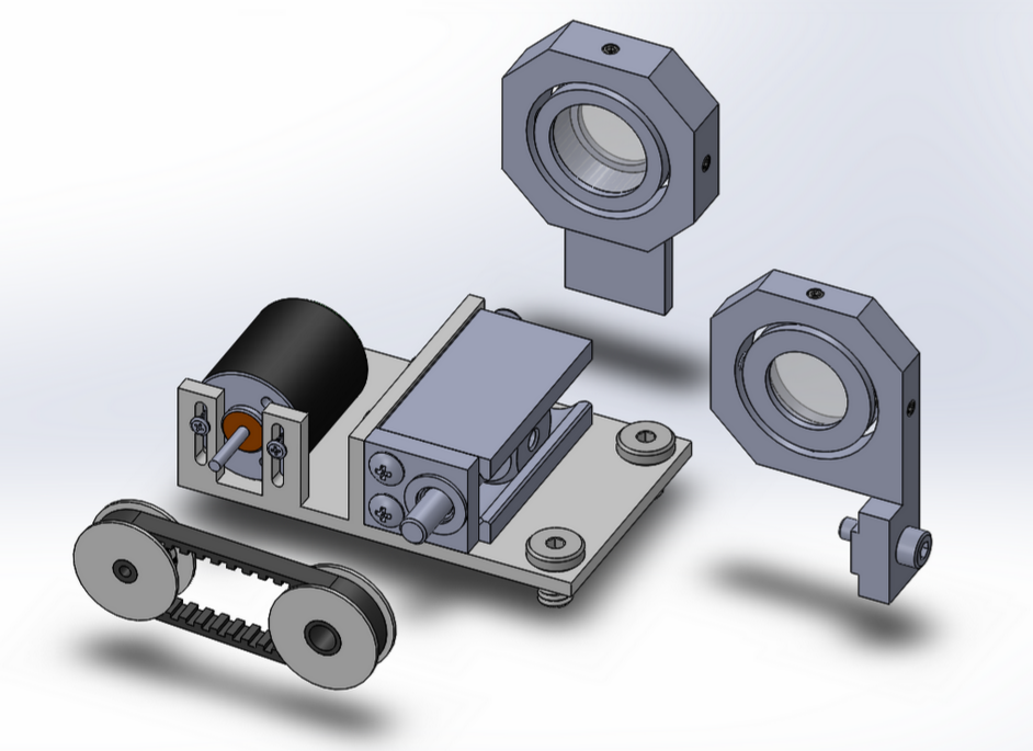 Figure 5: The current mechanical assembly, consisting of a stepper motor driven belt-drive, rotationally driven linear translator, custom lense mounts, and custom assembly mounting plate.
The following is a list of the components used in this design solution. This list will be modified as we come up with a solution to replace the belt-drive.
- Edmund Optics 53-383 Precision Translation Mechanism:
http://www.edmundoptics.com/optomechanics/positioning-stages-slides/leadscrew-travel-stages/in-line-precision-stage-mechanism/2093/
- Faulhaber AM1524 2-phase Stepper Motor:
http://www.micromo.com/am1524-a-45-3-6-04.html
- McMaster-Carr MXL Timing Belt and Pulley Power Transmission System (SUBJECT TO CHANGE):
http://www.mcmaster.com/#timing-belts/=wxpz0b
http://www.mcmaster.com/#timing-belt-pulleys/=wxpze2
- CUSTOM Lens Mounts and Assembly Mounting Plate (See assembly drawing above).
- Fasteners:
http://www.mcmaster.com/#socket-head-cap-screws/=wxq0hr
http://www.metricscrews.us/index.php?main_page=index&cPath=98_2
CONTROL SYSTEM
The control system will take use of 4 main components: the Arduino Due microcontroller, an LCD keypad shield, a stepper motor driver, and a microswitch position feedback system. Below is a block diagram for the control system:
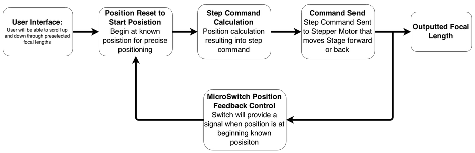
Figure 6: Functional block diagram of the control system.
The user will select a focal length from a list of choices of focal lengths. Once a focal length is selected, the stage will translate the dynamic lens to a starting position indicated by a signal from the microswitch. Once at this position, the microcontroller will calculate the needed number of steps to achieve the right distance between the lenses for a specific focal length. That number of steps will be sent to the stepper motor driver that will control the stepper motor to step the calculated number of times. After the motor has stepped the needed number of times, the dynamic lens will be at the right distance from the static lens producing the needed effective focal length. Below are links to the components we will be using:
- Arduino Due Microcontroller:
http://store.arduino.cc/product/A000062
- Sainsmart Keypad LCD Sheild:
http://www.sainsmart.com/arduino/arduino-shields/lcd-shields/sainsmart-keypad-shield-1602-lcd-module-v3-display-for-arduino-mega-2560-1280-uno-r3.html
- EasyDriver - Stepper Motor Driver:
https://www.sparkfun.com/products/12779
- Omron Snap Action Switch:
https://www.sparkfun.com/products/98
| FIRST SEMESTER | |
|---|---|
| March |
|
| April |
|
| SECOND SEMESTER | |
| September |
|
| October |
|
| November |
|
| December |
|
Project Progress:
- Week of 1/19/15 - Projects and Groups were selected, first meeting together and with advisor.
- 2/3/15 - First meeting with Quantel. We were introduced to the laser system that we will be working with. Broad specs were introduced to help start on design.
- 2/5/15 - Decided on areas of research for project. Talked about resonator cavity and the basic ideas for lens systems with David.
- Week of 2/9/15 - Background research done and discussed. Design choices brainstormed and listed with alternatives.
- 2/12/15 - Second meeting with Quantel. Learned the physics of thermal lensing. Also learned more constraints pertaining to the laser cavity space and size of beam.
- Week of 2/12/15 - Worked on research for design alternatives and a few quantitative analyses for some design choices.
- Weekend of 2/13/15 - Worked on MATLAB scripts to help model different lens systems through ABCD matrices to help decide on a specific lens system. Initial tests and results were dissatisfying. Rework of MATLAB code to come.
- 2/15/15 - Linear Actuation chosen. 6061 Aluminum chosen. 2 lens system chosen. Two button microcontroller system chosen.
- 2/24/15 - List of detailed design specs obtained.
- 2/28/15 - MATLAB script worked on by team. Tested 50 different design options and were left with three that will work. A -30mm and +30mm focal length lens system was chosen as best option.
- 3/2/15 - Preliminary Design Report presented. Overall went very well.
- 3/6/15 - Chapters 1-5 of Design Report worked on and turned in.
- 3/13/15 - Webpage first draft is made live.
- 3/16/15 - Actuation stage and device options discussed by team.
-
3/23/25 - Team meets in optics lab for prep for Critical Subsystem Demo.
-
3/29/15 - Demo preparation shows flaws in our optics design. The flaw is a result of mistakes made in MATLAB. A rework is done with lenses available in the lab. -75 mm and 100 mm lenses are chosen as best available option for the demo.
-
3/30/15 - Critical Subsystem Demo performed with good results.
-
4/2/15 - Detailed Control System research performed, multiple options for the parts are found.
-
4/9/15 - New lens system decided on: -55mm and 65mm lenses.
-
4/16/15 - Preparation for Critical Design Review started.
-
4/18/15 - John and Spencer develop full translation system assembly in SolidWorks.
-
4/20/15 - Critical Design Review presentation went well. Few things were noted to take a look at.
-
4/23/15 - A detailed look into our lens system is performed in Zemax.
- 4/27/15 - Group webpage updated to include team bios, design content, and progress to date.
Copyright © DCTS Design Team. All rights reserved.
Design and layout by John Mulford.