NSF Acoustic Recording Collar

Project Overview
The goal of
the project is to create an observation collar for marmosets to operate in the
wild.� The collar will record information
such as sound, localized movement (such as acceleration), and GPS
location.� All of this information will
be processed by an FPGA and then stored to a microSD flash card.� The collar will be battery power and solar
cell charged.
������������������������������������������������ Group
Members:� Kyler Callahan (CompE),
Justin Marquart (EE)
������������������������������������������������ Advisor:
Ross Snider
������������������������������������������������ Sponsor:
National Science Foundation
Project Goals
����������� Marmosets
are very small animals; because of this our project has some constraints.� It needs to be as small as possible, and as
power efficient as possible as we cannot use very large batteries of solar
cells.� We will be modifying an existing
prototype of the collar
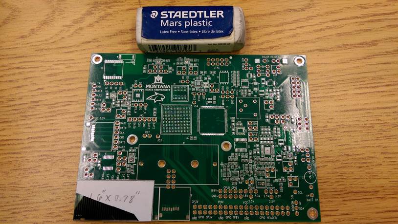
������������� The
first prototype (picture above) is 4.75inx3.5in.� To fit this on a monkey the board needs to be
shrunk down considerable.� To do this a
lot of unnecessary parts will be stripped out, and the PCB will be
re-worked.� The new PCB will be split into
3 segments, each a size of 0.78inx1.6in. The first prototype board will aid us
in picking out a battery and learning how to work with solar cells.� The knowledge gained from this will help us
design the collar.
Kyler Callahan will be doing the PCB
design for the collar, while Justin Marquart will be studying the batteries and
the solar panels for application on the collar.
Project Status
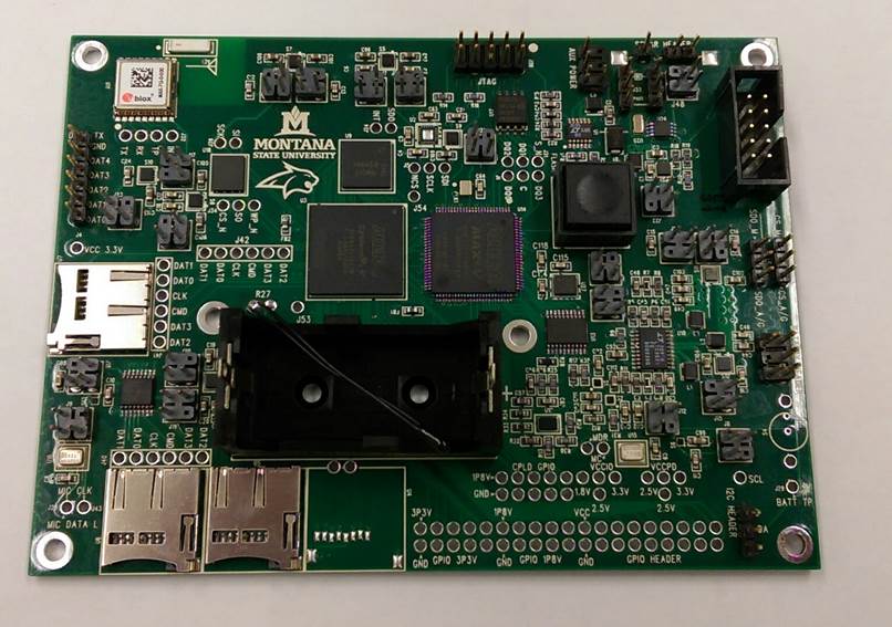
������������� This
project consists of two parallel developments.�
This first is a prototype board that will inform us how our design
works.� The second development is to
create a second iteration of the initial prototype.� These two things can be done in parallel as
the components for the first prototype are finalized and board design is very
time consuming.� Pictured above is the
completely assembled version of our first prototype.� We are currently testing it for design
errors.
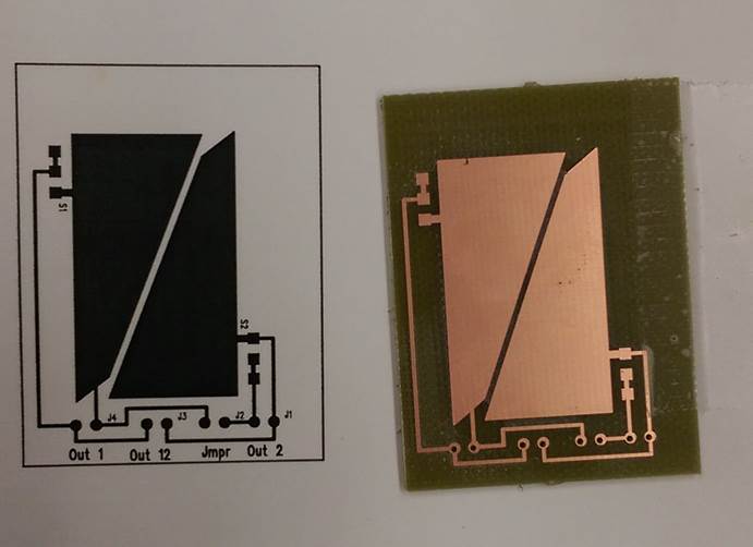
������������� To
make the testing of the solar cells we needed to create a board which houses
the cells.� Pictured above is a single
layer PCB fabricated here at MSU, this will house the solar cells we will be
testing.
������������� The
prototype will be split up into three PCBs: one housing the power components
called our POWER board, one housing our sensory components called our SENSOR
board, and one that houses our FPGA and all of its essential components needed
to operate will be called our MAIN board.�
The three boards will be connected with a FFC cable.
 �
�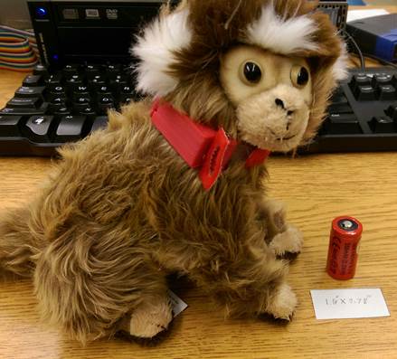
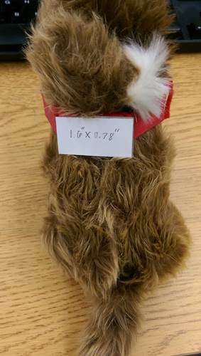
������������� Above is a stuffed marmoset that
is slightly smaller than the actual animals we will be designing for.� We have a first design collar based on the
solar cell dimentions.� This initial collar
is too small to house our PCBs so dimentions will need to be adjusted
appropriatly.� The white piece of paper
is representing the size of the PCB we will be using.� This size has been determined by the absolute
minimum allowable size needed to house the FPGA and all of its essential
comonents.� The battery we will be using
is also presented for size comparison.
������������� Finally
we the PADs Layout rough draft of our main board that houses the FPGA and all
of its essential components.� Nothing is
hooked up yet as the other two boards need to be finalized.� However this is very close to what our MAIN
PCB will look like.